Regen Setup

Sizing code to determine engine geometry and performance characteristics
To understand how a regen engine will look and operate several conditions need to be defined first, such as the propellant, liner material, burn time, and other conditions. Eventually for typical sizing conditions to continue, temperatures inside the coolant channels, on the liner, and heat transfer coefficients need to be found. This requires understanding four values, coolant heat transfer coefficient, wall heat transfer coefficient, coolant temp, and hot gas temp.
This in turn requires a Newton Raphson numerical analysis system needs to be developed. This requires putting in guesses for the values and making a computer program that can converge to a point of agreement for these values which I have developed to verify the one used by a master's student.
CFD Analysis

Temperature Results from CFD
For trying to see if our data matched a simulation, Ansys thermal was used to find temperatures in the chamber given what was known and evaluate if the model was working correctly. This involved running many simulations depending on what was being looked for and allowed one to find areas that were likely to see failure as a result. Once areas are found solutions can be brainstormed and implemented to see how they can affect the resultant thermal analysis. An example of this is the implementation of film colling as early on it was determined that regen cooling may not be able to sustain the expected thermal stress on the liner. After this had been implemented, a substantial drop in chamber pressures could be observed.
CAD Setup
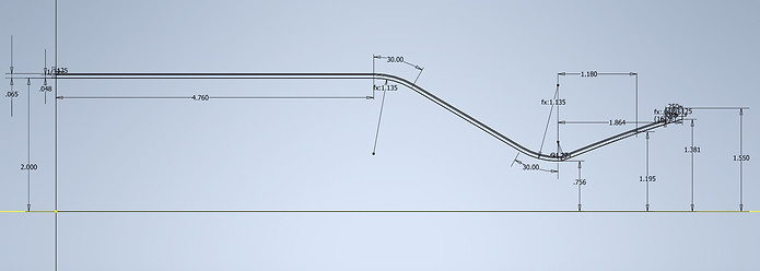
Because the size of the channels is expected to remain constant at all points in the liner, the ribs in between must become smaller as it approaches the throat. To model this, a parametric system was developed using Inventor that considered inputs at the chamber, throat, and exit with an equation being used to describe the changing geometry between these points. This allowed the CAD to be easily updated as all one had to do was change a value to auto-update the rest of the system. This allows our CAD models to rapidly change to accommodate changes from our code.